










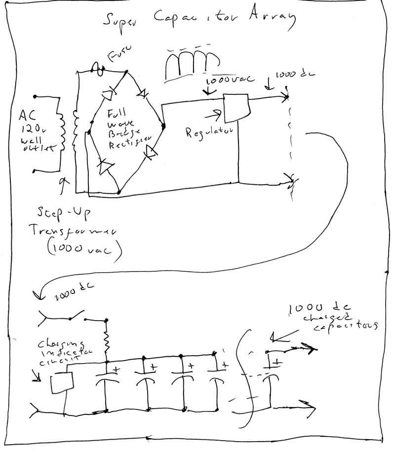
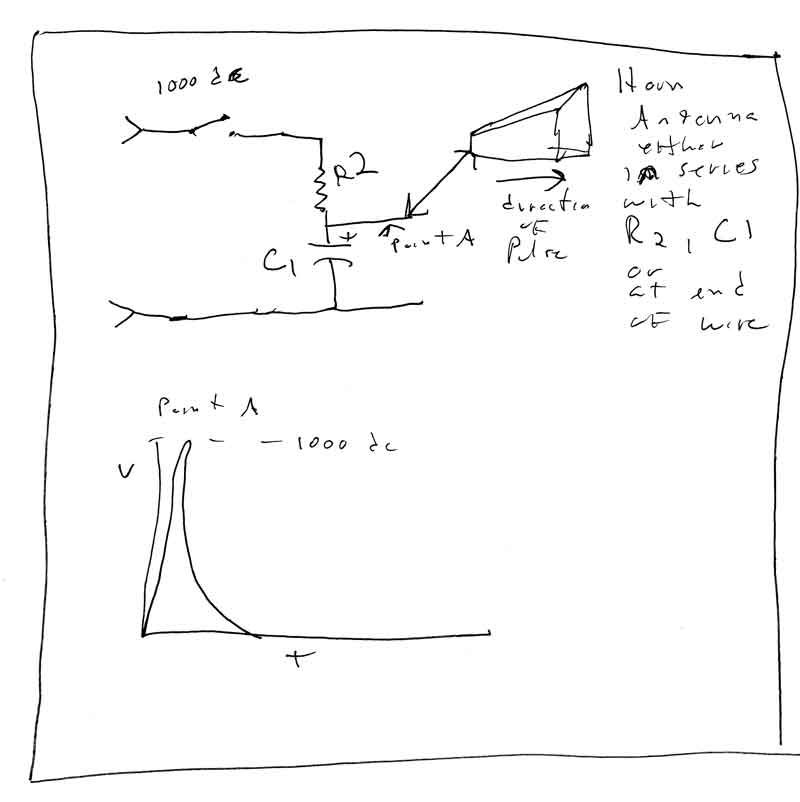
Second Addendum Added Dec 7 2016 - This addendum is an attempt to fix some of the issues brought up in the 'Problems' section above. The original design will pull down the DC voltage as the pulse rises. The overall wattage will be affected. This design adds an array of super-capacitors as a power source for the pulse. Super-capacitors are designed to hold a large amount of energy at high ratings such a 3500 volts. The definition of a capacitor is that it stores energy in an electric field. It can act something like a battery. It can be charged then discharged. The idea is to replace the AC supply and regulator with a an array of super-capacitors. The capacitors are charged through a resistor. When the capacitors are fully charged an indicator circuit lights. The resistor and AC supply circuit can then be removed by throwing a switch. When ready, another switch is thrown to discharge the capacitors into the antenna circuit. After discharge the antenna circuit is switched out and the capacitors charged again.
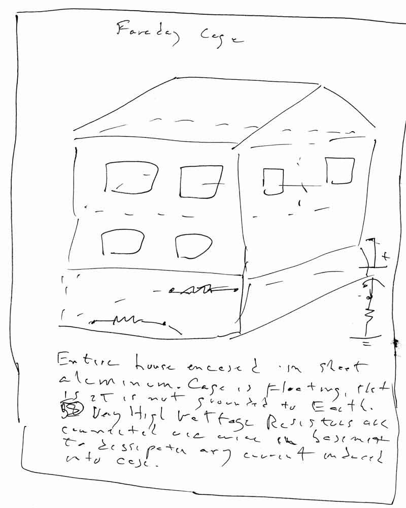
This is some observations about Faraday Cages. Very Low Frequency emissions can penetrate a lot. Its possible a Faraday Cage won't stop VLF. This is some potential solutions. Encasing a house in sheet would be better than mesh. In the event VLF penetrates sheet it might be possible to 'float' the cage, by not connecting it to Earth ground. Instead the entire cage will act like the secondary of a transformer and a current will be induced into it. To move and dissipate that current it needs a load. The first idea is to connect a couple very high wattage resistors in the cellar. The other idea is to connect the cage to Earth ground through a capacitor or resistor or both to help dissipate the current. (see picture)
